 Help
Help
Bilbao Crystallographic Server
 Help Help
|
The Brillouin zones are projected onto the drawing plane by a clinographic projection. The coordinate axes are designated by kx, ky and kz; the kz-coordinate axis points upward in the projection plane. The diagrams of the Brillouin zones follow those of CDML [1] in order to facilitate the comparison of the data. The origin O with coefficients (0, 0, 0) coincides always with the centre of the Brillouin zone and is called Γ (indicated as GM in the k-vector tables).
In the Brillouin-zone figures the representation domains of CDML are compared with the asymmetric units of ITA [2]. If the primitive basis of CDML {g1, g2, g3} and the ITA basis {kx, ky, kz} do not coincide then their relations are indicated below the Brillouin-zone figures. A statement if the representation domain of CDML and the asymmetric unit are identical or not is given below the k-vector table. The asymmetric units are often not fully contained in the Brillouin zone but protrude from it, in particular by flagpoles and wings.
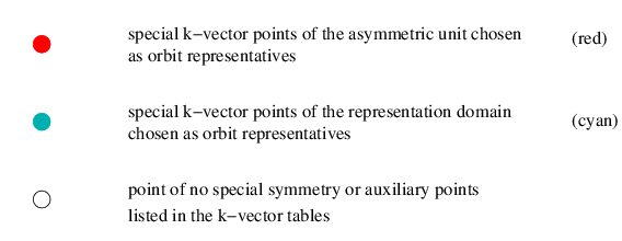
In the figures, a point is marked by its label and by a circle filled in with white, if it is listed in the corresponding k-vector table but is not a point of special symmetry. The same designation is used for the auxiliary points that have been added in order to facilitate the comparison between the traditional and the reciprocal-space group descriptions of the k-vector types. Non-coloured parts of the coordinate axes, of the edges of the Brillouin zone or auxiliary lines are displayed by thin solid black lines. Such lines are dashed or omitted if they are not visible, i. e. are hidden by the body of the Brillouin zone or of the asymmetric unit.
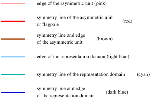
The representatives of the orbits of k-vector symmetry points or of symmetry lines, as well as the edges of the representation domains of CDML and of the asymmetric units are brought out in colours.


The labels of the special lines shown on the Brillouin-zone figures are always red or cyan irrespectively whether the lines are edges of the representation domain or not. Common edges of an asymmetric unit and a representation domain are coloured pink if they are not symmetry lines simultaneously.
Flagpoles are always coloured red, see, e. g. the line P1 or PA1 in the figure of the acute case of the space group R3 (No. 146). Symmetry planes are not distinguished in the figures. However, wings are indicated in the figures and they are always coloured pink, see, e. g. the Brillouin zone figures of C2/c (No. 15) for unique axis c and unique axis b settings.
|
Bilbao Crystallographic Server www.cryst.ehu.es |
For comments, please mail to administrador.bcs@ehu.es |